Optimized Concrete Testing

Click on any image for the journal article discussing this research in detail.
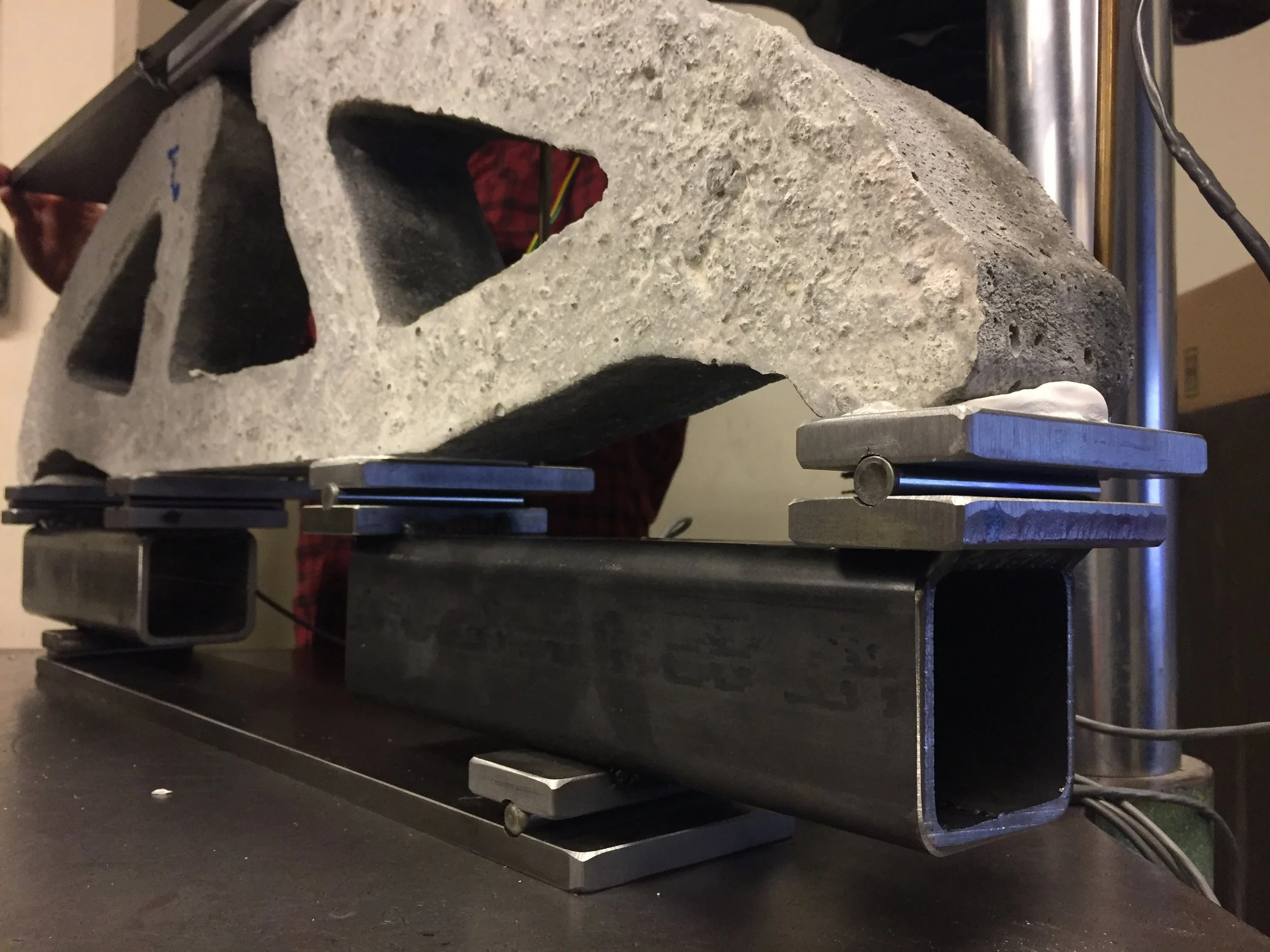
For my Master’s Thesis, I designed, fabricated, and tested plain concrete beams using topology optimization. To carry out the tests, we built a custom testing apparatus to deliver our atypical load conditions into our concrete specimens.

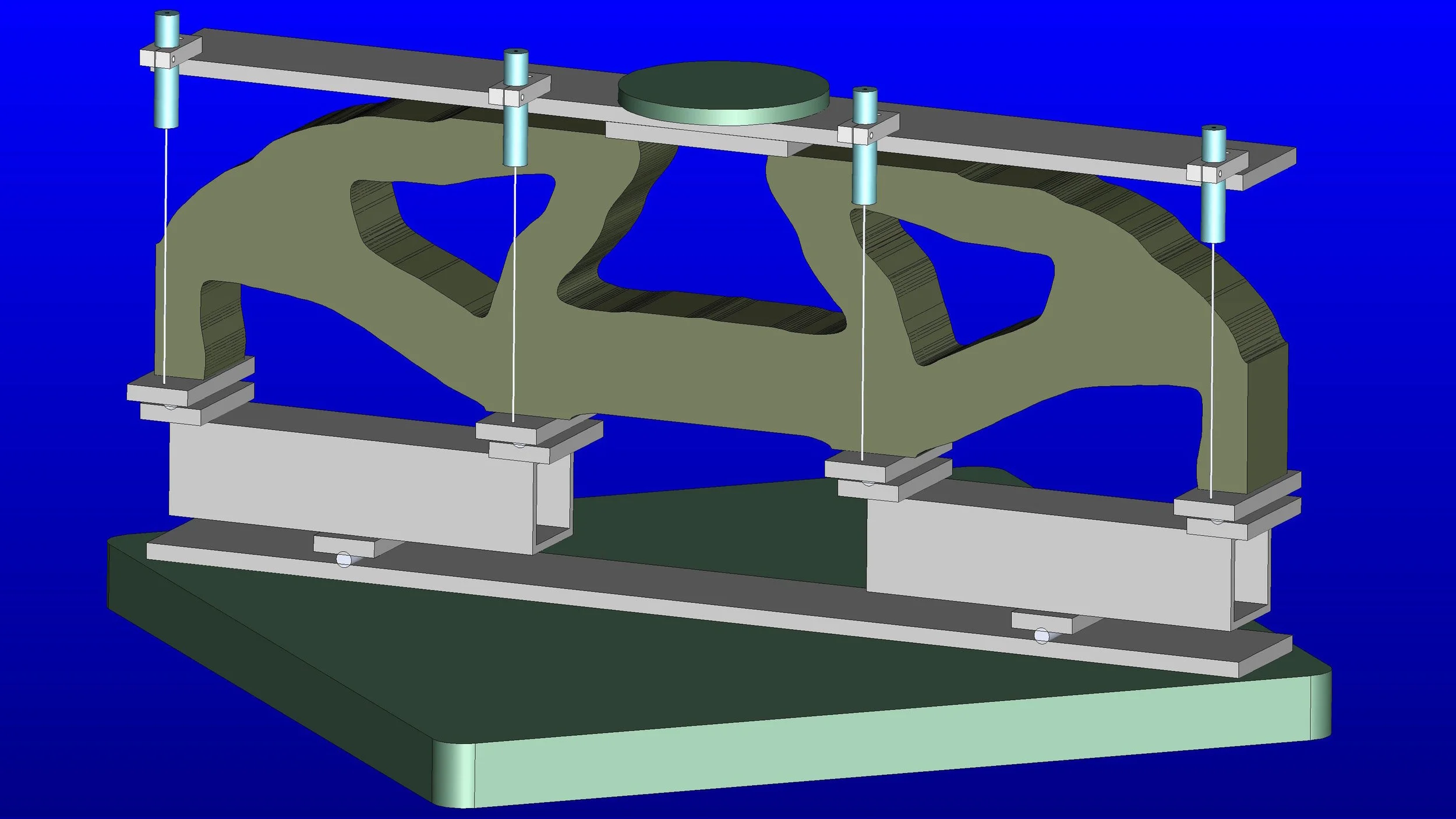
After building a CAD model, steel was ordered, cut down to size, and assembled using the tools in the CEE machine shop.


To ensure even load application, rods were used to act as rockers, so slight deformations would not alter the force flows of the system. Components were cut, milled, and welded together using an inert gas metal arc system.

I learned how to use a dozen tools and machines in our shop to bring all the components together into our testing apparatus.

Milling Steel
Components were milled to the 1/1000 inch accuracy using automated equipment in the lab. The mill in this video is imperceptively moving horizontally, in real time.

4 LVDT Sensors were placed in line with the point loads so the compliance of the system could be measured. Above is an image of a control specimen we fabricated for comparison against our optimized beams.

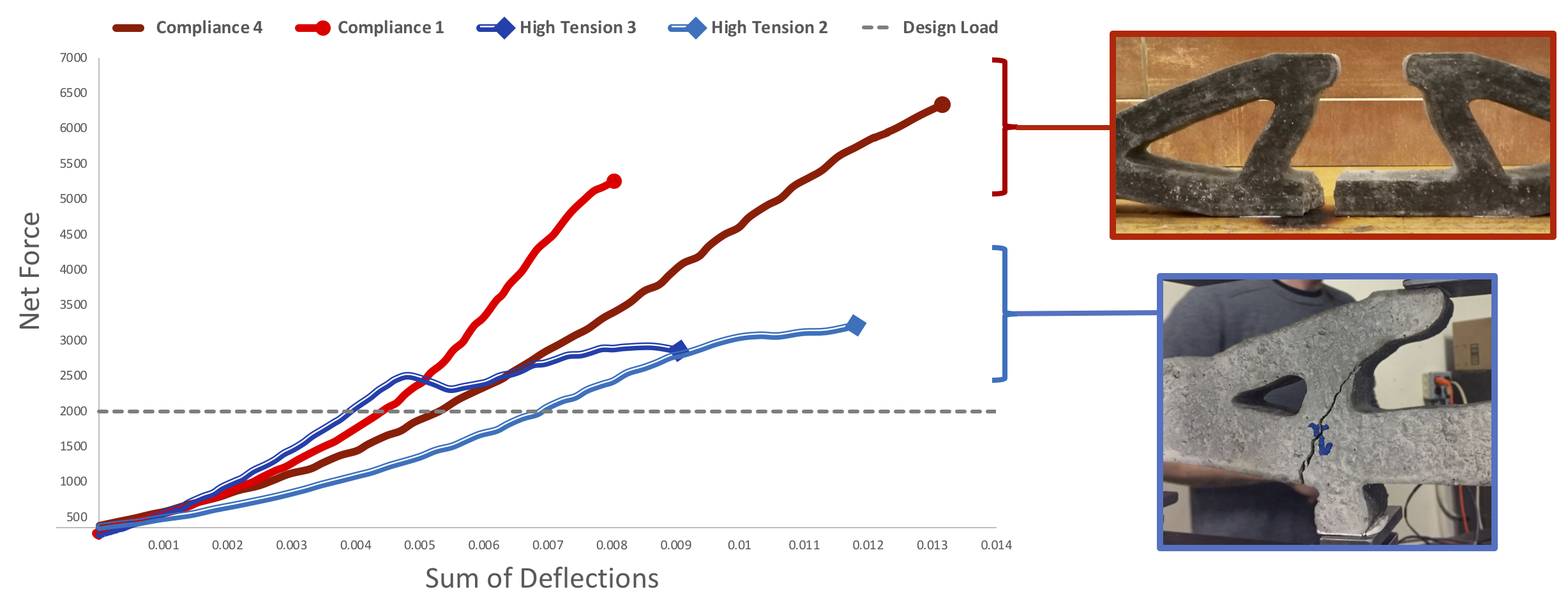
We tested 15 different specimens, as well as 16 concrete cylinders in both tension and compression. We analyzed the data we collected to understand the results of our experiment.


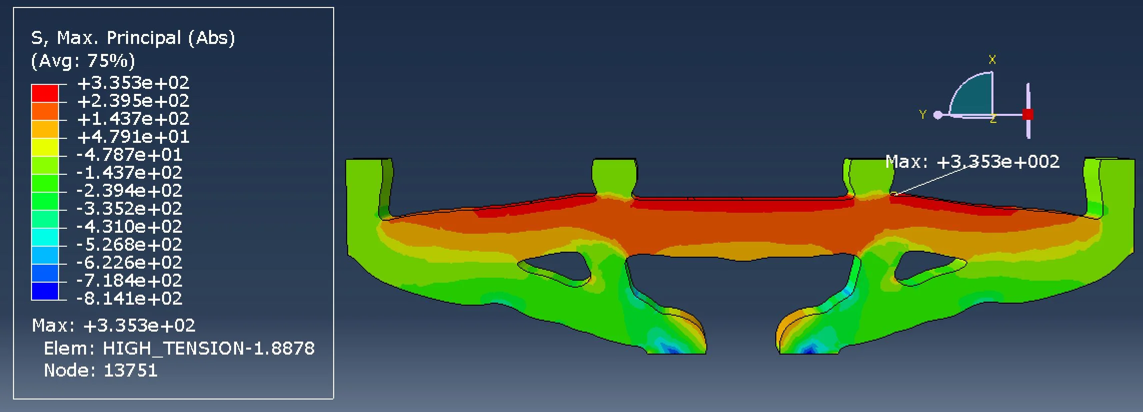
To understand the failure patterns in the concrete, we modeled the forms in Abaqus and simulated our loading conditions. The Finite Element Analysis helped illuminate the internal stresses of our beams upon failure.

Force-Deflection Diagram of optimized concrete Beams
The results of these experiemnts are summarized in this paper, published by Automation in Construction in February of 2019:
Jackson L. Jewett, Josephine V. Carstensen, Topology-optimized design, construction and experimental evaluation of concrete beams, Automation in Construction, Vol. 102, 2019, P. 59-67